
Supercharger Installation Guide
Supercharger Installation Guide
(Last Revision 31/12/2021)
It’s worth noting before we start. That the kit used for this guide is the very first prototype kit that paved way for the retail kits we ship out. Therefore some of the components are not as cosmetically pleasing and will be different compared to the kit you will receive
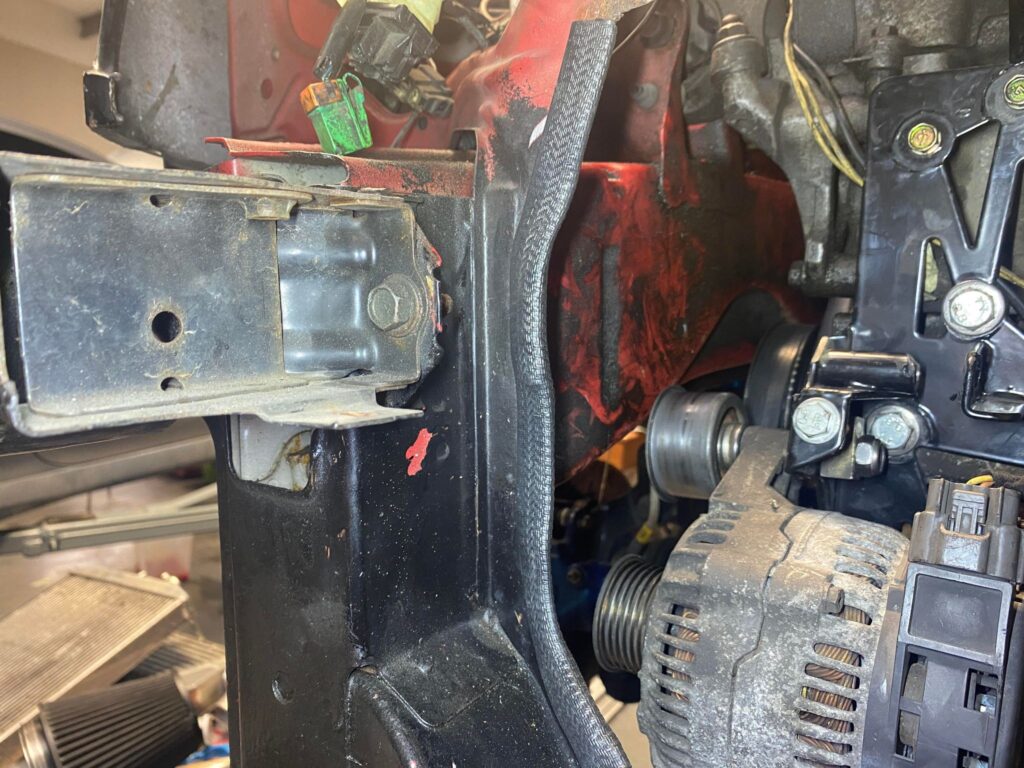
First, Remove the Alternator and Throttle body.
We will be re-using both of these components, so keep them to one side and retain the nuts and bolts they used.
With the throttle body off, now is the time to extend the coolant hoses and extract the plugs for the MAF and TPS Sensors. It’s important to do this now as it will be difficult to do this when we start to install the supercharger kit.
It will also be easier to install your fuel injectors at this stage.
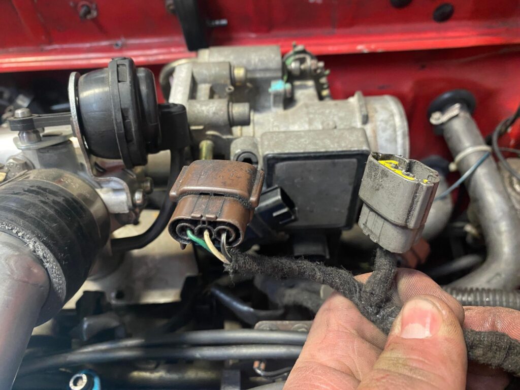
The plugs for the MAF and TPS Sensors are taped in with the injector wiring loom. Unwrap the loom and pull the 2 plugs picture below out from the loom so the plugs can reach the throttle body in its new location then Re-tape the looms.

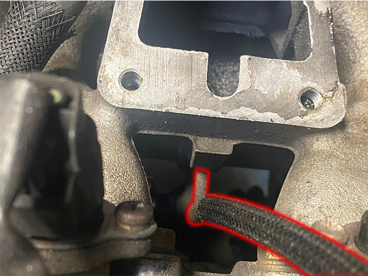
Next we need to extend the coolant bypass hoses for the idle air control valve on the throttle body. Once again it is important to do this now as it will be difficult to do this when we start to install the supercharger kit.
The two hoses in question are highlighted in RED.
In the picture you can see we have simple extended the hoses, however is it recommended to replace both of these hoses are their origins. We have provided enough hose in the kit to do this.
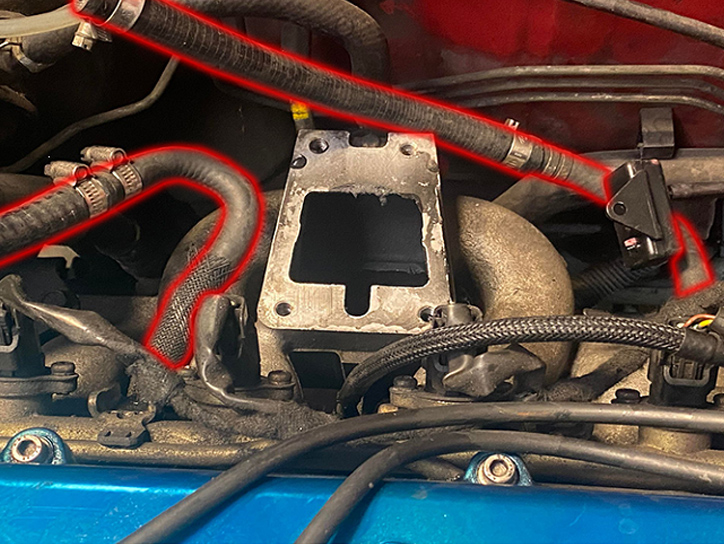
The hose on the LEFT connects to the coolant bypass pipe that runs along the back of the engine, under the inlet manifold.
The hose on the RIGHT connects to the cylinder head, approximately under the fuel pressure regulator.
Follow the hoses and you will easily find the origin of both hoses.
New hose clamps are provided.
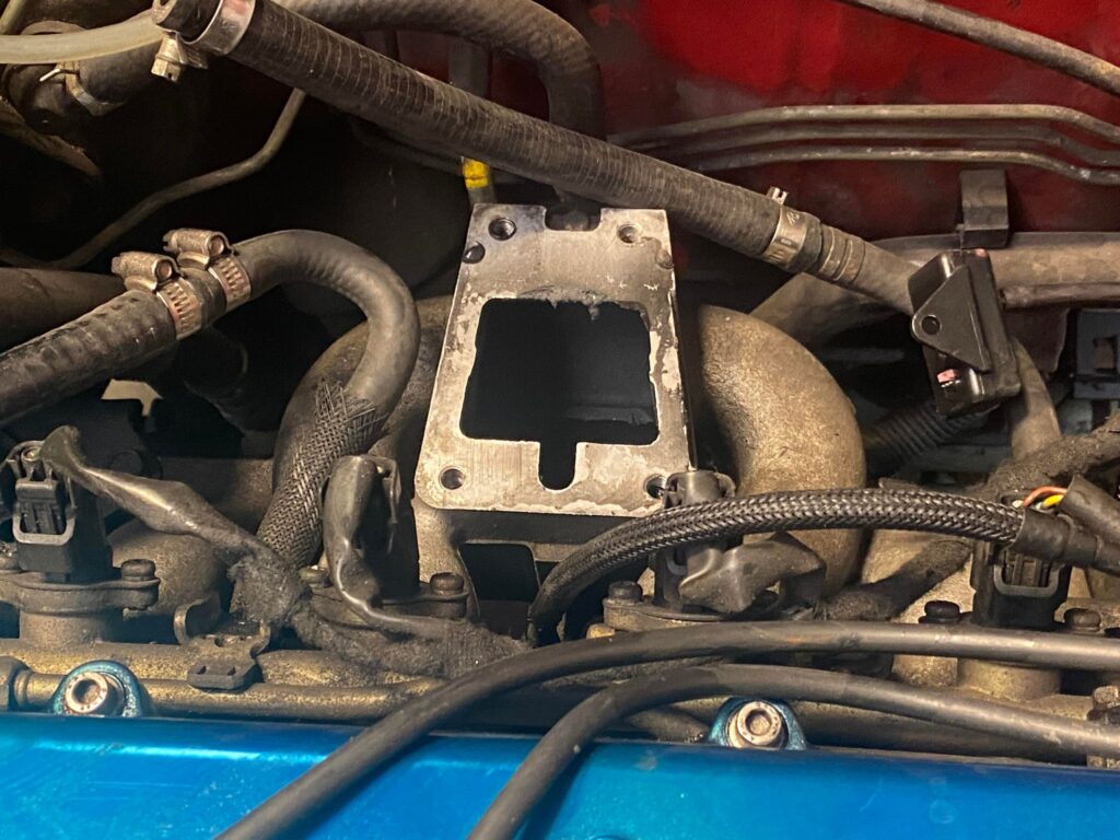
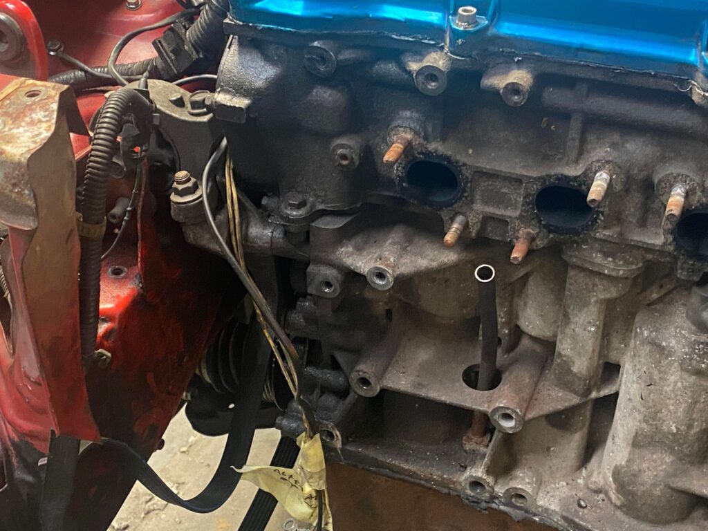
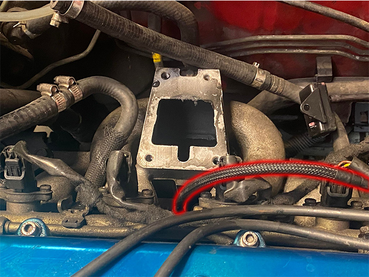
Next, replace this vacuum hose with the longer length supplied in the kit as it will be difficult to install once we start to install the kit, don’t worry about cutting it to size for now.
If you are running an ECU for management and not an FMU, you could skip this step. But we would recommend replacing the vacuum line anyway whilst you are here.
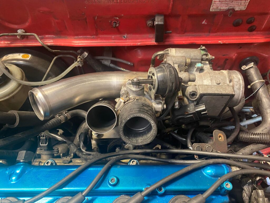
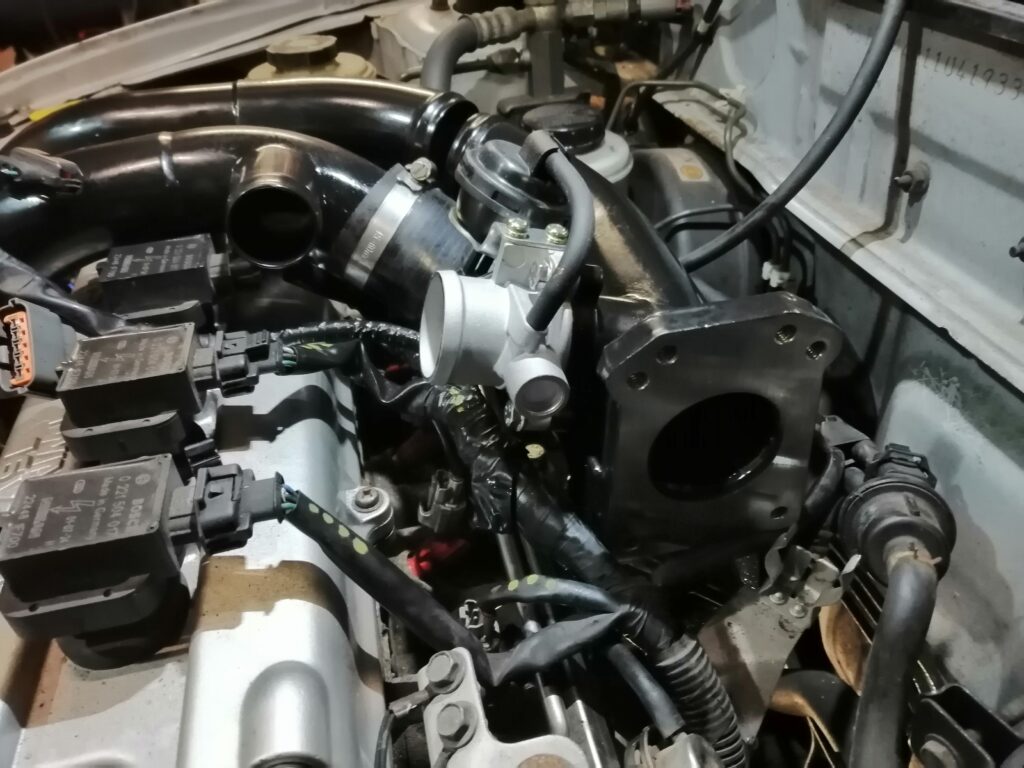
Next, install the throttle body and the bypass valve onto the tower bracket.
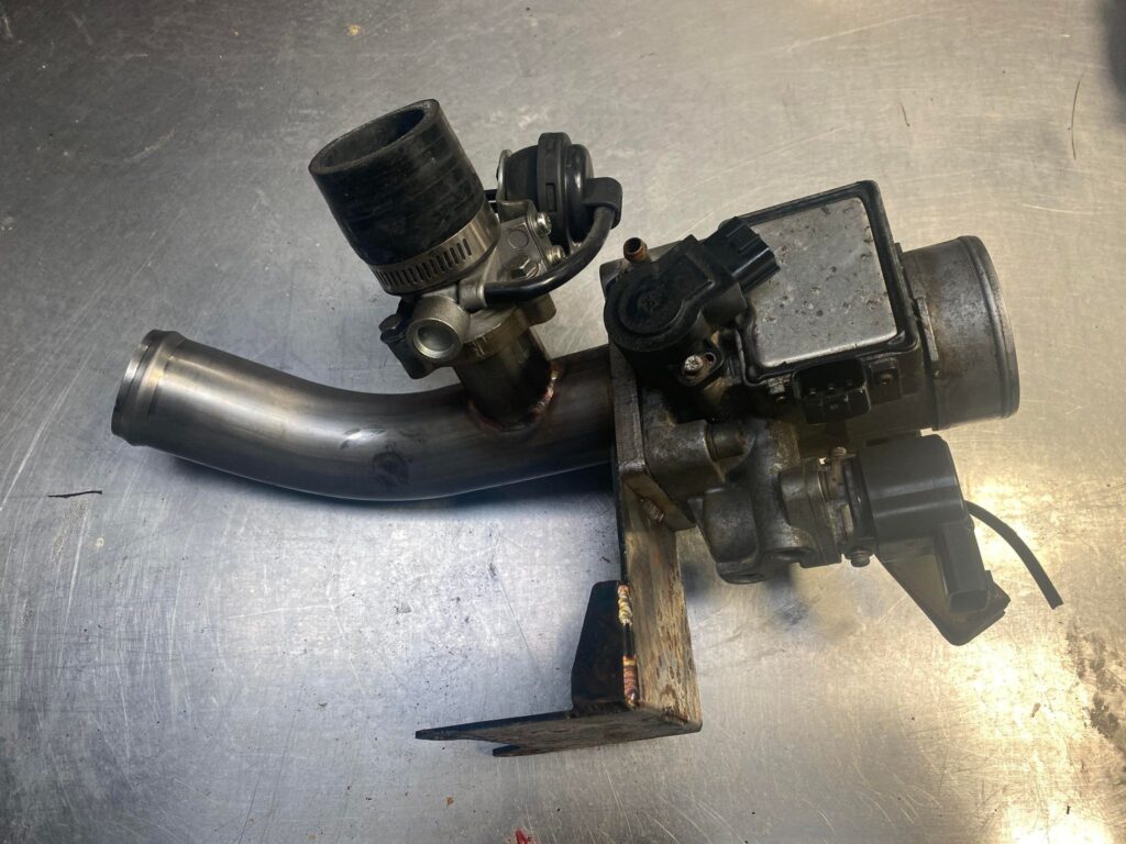
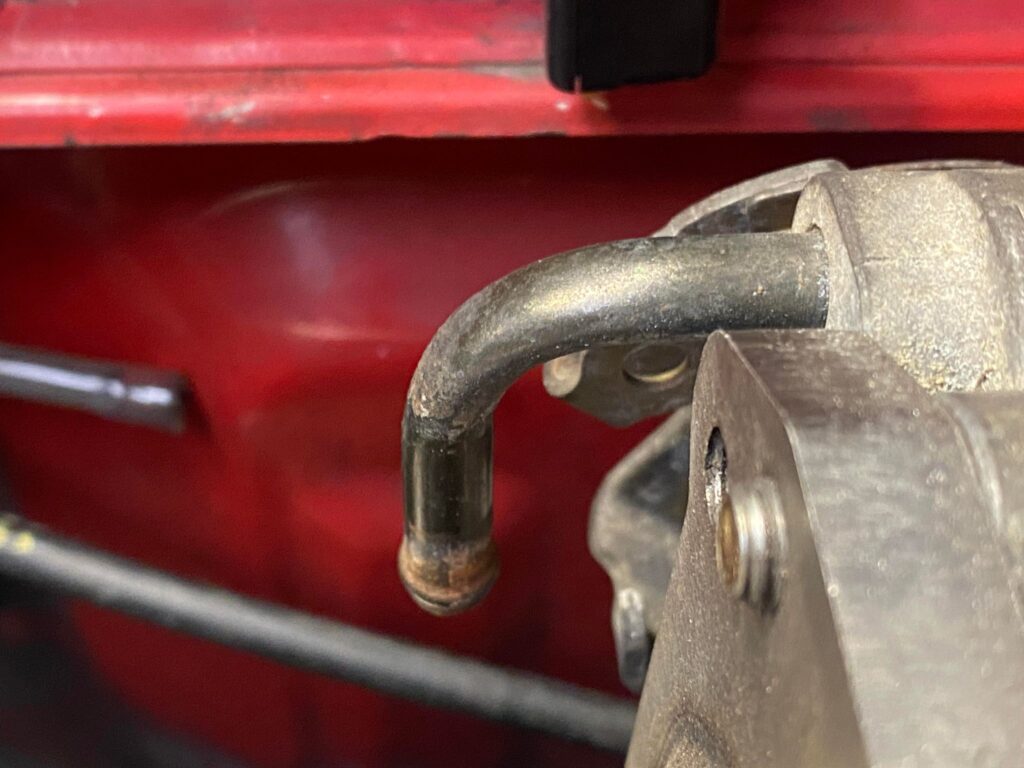
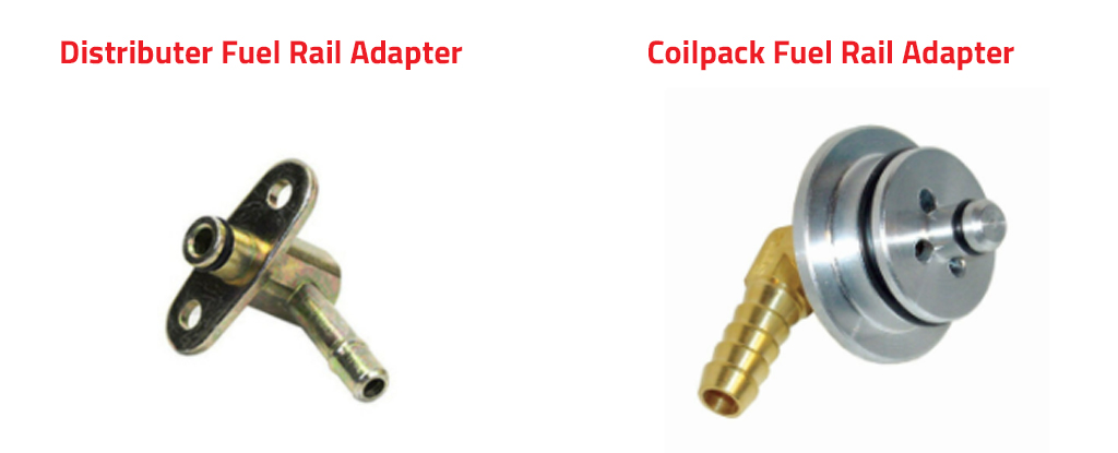
Before installing this assembly, we need to modify the coolant outlet on the throttle body. If you have a Distributer model, you will have this elbow as pictured below. By default this would point towards the firewall, however we need it to point down. The fitting is an interference fit and in most cases can simple be rotated with a bit of force. In some cases we would recommend heating up the local area. This should make the fitting easier to rotate.
If you have a coil pack, instead of the elbow, it will be a strait fitting. You can simply cut the barb down at the secondary barb in the middle.
Now let’s start to install everything.
The elbow adapter and the tower bracket sandwich together using the same 4 bolts. Place a gasket on the manifold, then the elbow adapter pictured below and then the tower bracket.
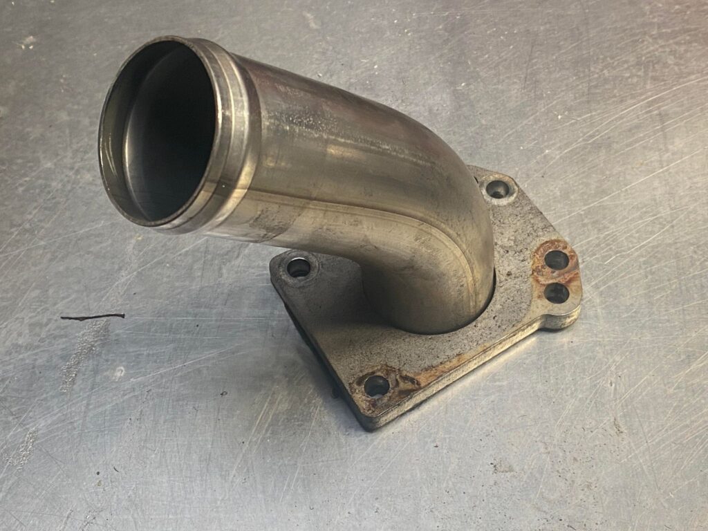
The install should now look like the above.
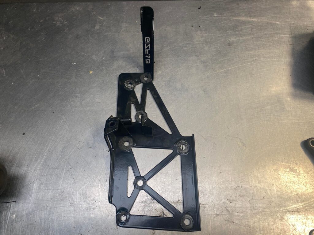
Next, install the supercharger bracket.
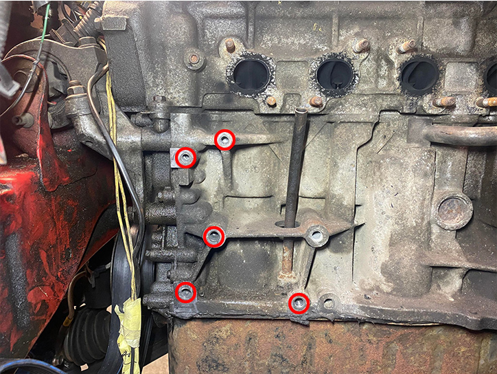
Ensure these 5 bolt holes are clear of debris. Clear the threads with a tap set.
Top 2 are M8 x 1.5,
Bottom 3 are M10 x 1.5
Take this opportunity to extend and route the alternator harness through the bracket to keep it clear of the rotating components.
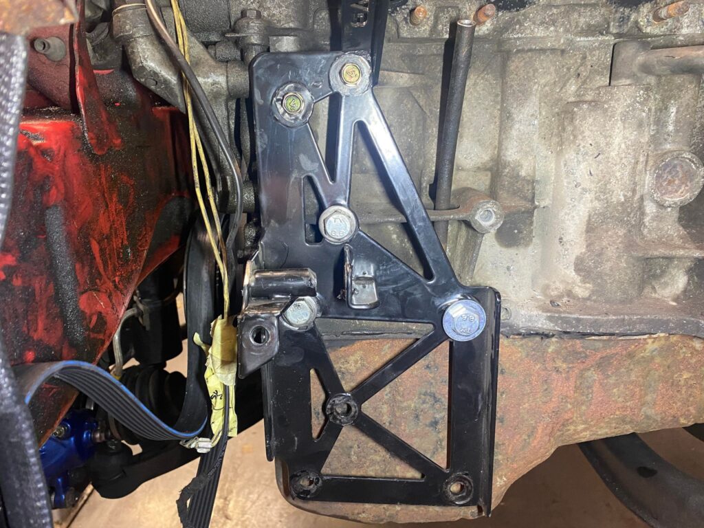
Now re-install the lower alternator bracket to the bottom of the bracket using the same bolts it was originally installed with.
Install the alternator on the lower bracket; do not fully tighten the bolts.
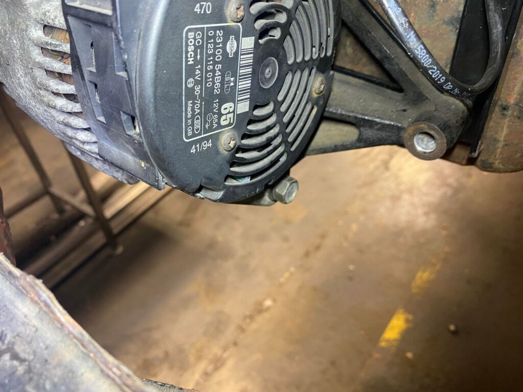
Next, fit the Earth cable. This cable must bolt to one of the alternator bolts – any of them, it doesnt matter with the other end to the engine block. Failure to do so will mean the alternator will not work and will not charge the battery.
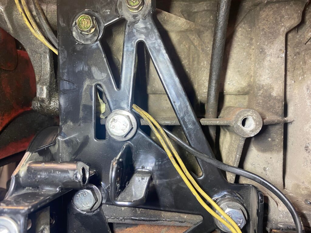
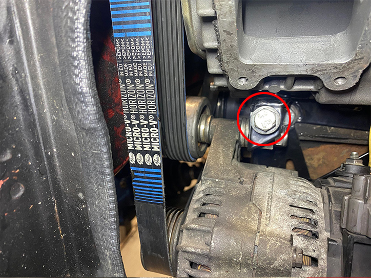
Next, install the tensioner idler, using the long M10 Threaded bolt and spacer washers. There are 6 Thick M10 spacer washers in the Kit, 1 goes inside the idler as a washer, 3 are then stacked in between the backside of the idler and the alternator, and a further two between the alternator and the bracket.
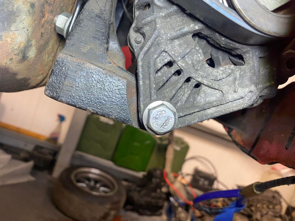
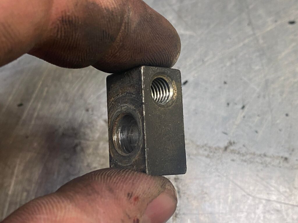
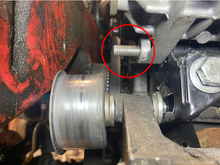
When you removed the original alternator brackets, there is a Fitting we need to salvage that formed part of the original tensioner system. Pictured below.
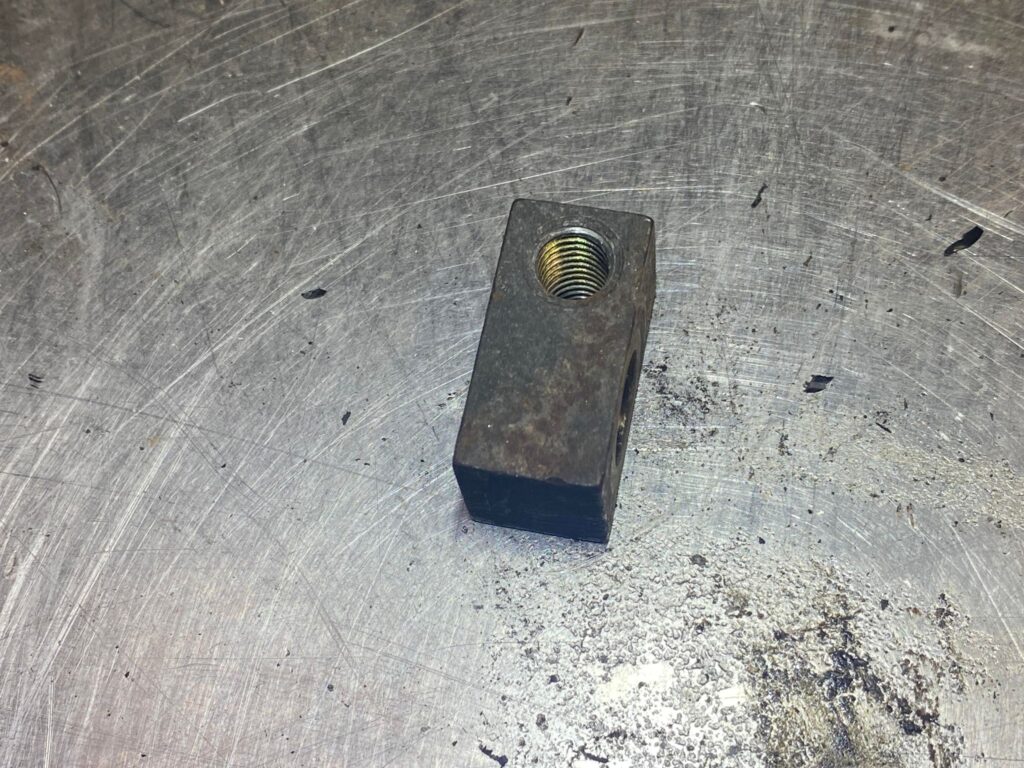
We need to modify this fitting. There is a M8 and M10 Thread. We need to drill out the M10 Threads as pictured below.
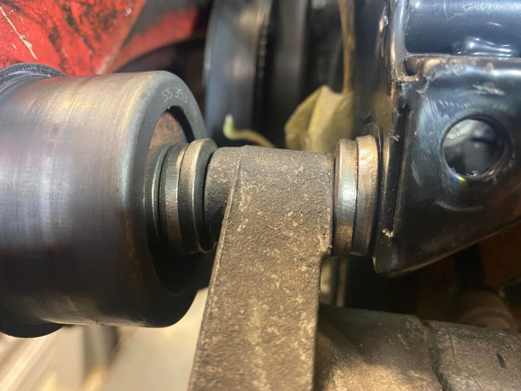
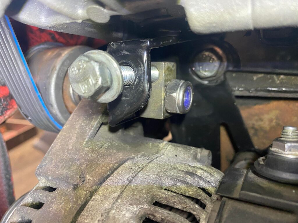
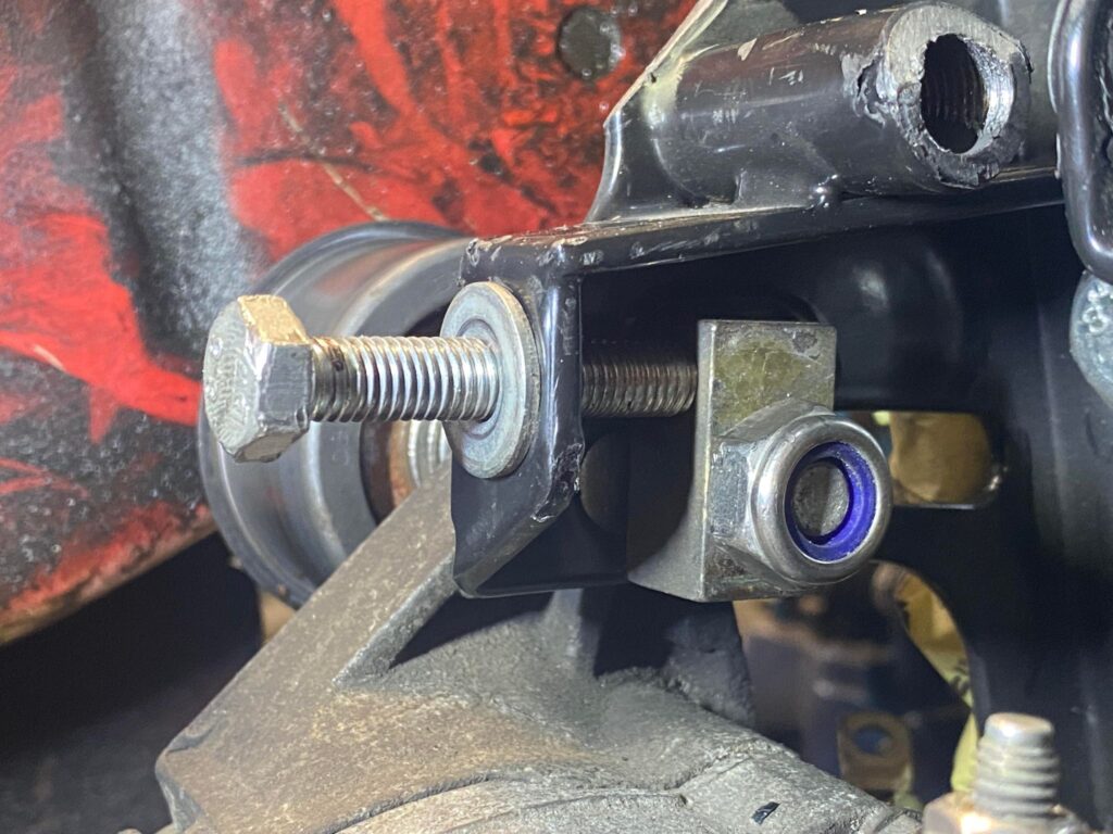
Now we can install this component onto the remaining exposed thread of the long M10 bolt. Use the M10 nyloc Nut. Tighten to remove most of the slack from the assembly but do not fully tighten this bolt at this time.
Next we can install the main tensioning bolt, An M8 bolt and a washer, assembly is pictured below for reference.
Now, let’s start looking at installing the supercharger.
It’s worth noting at this time, we would recommend trimming the front panel, this will make install easier with more room to work with.
Below is a reference of we have trimmed the panel.
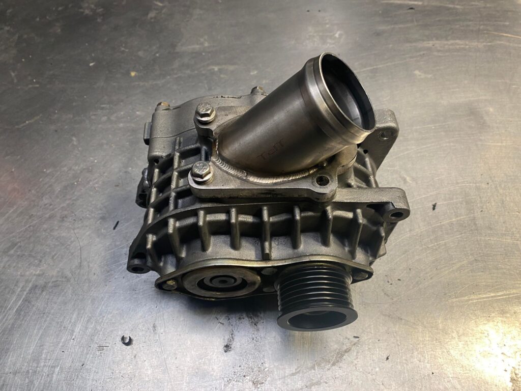
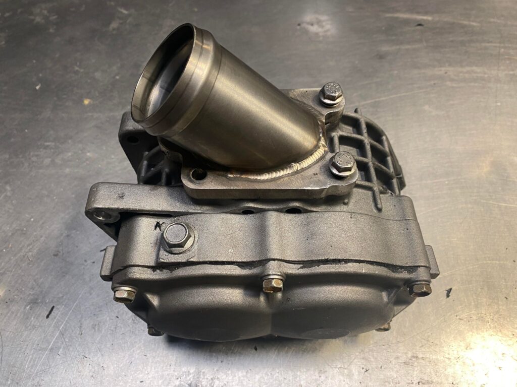
Install the upper inlet adapter on the supercharger unit as. Pictured below.
This will be extremely to install once the supercharger it in situ.
Do not install the other side at this time.
Before we install the supercharger, we need to install the gear oil as this cannot be done when installed. Unfortunately due to restrictions on shipping liquids and fluids, we cannot supply this for you.
Fill with 125mm of 75w90 Synthetic Gear Oil. Ensure to use a quality branded oil. There are also specialist gear oils available for supercharger applications. The fill plug is located on the top of the unit.
Now we can install the supercharger into the bracket.
There is a long M8 bolt that’s threads through from the backside of the charger and a short m8 bolt and nut on the top of the bracket to support the upper part of the charger. Make sure to use washers!
Install an M8 nyloc nut and washer onto the end of the bolt on the opposite side of the assembly.
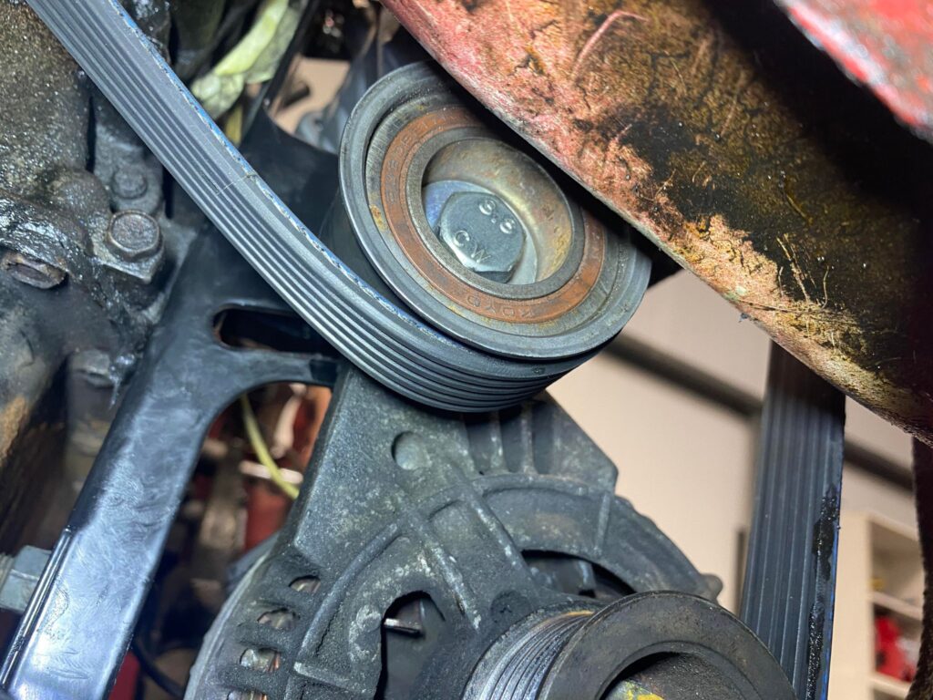
At this stage, we can now loosely install the belt.
Before installing the belt, ensure all 4 pulleys are free of debris, dirt and grease. Failure to do so will instantly contaminate the belt and may cause the belt to slip.
The belt routes as follows
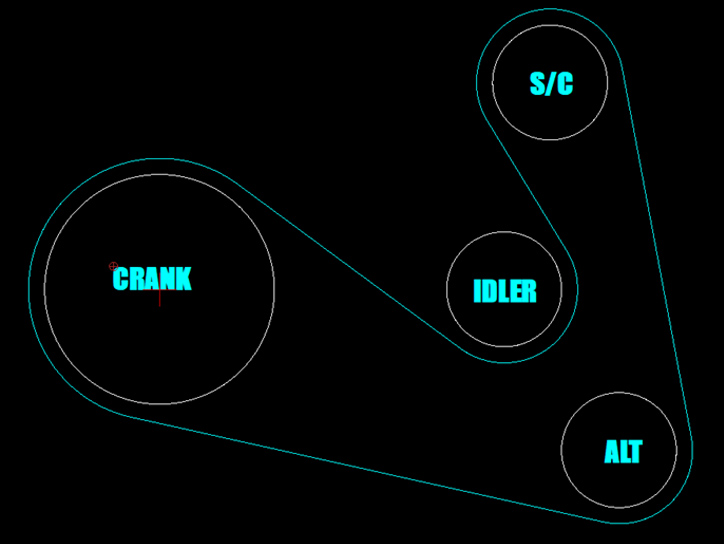
Now, we can tension the belt.
Using a 13mm, Tighten the M8 tensioner bolt. The belt should be tight enough so that the belt cannot be folded over 90 degrees.
DO NOT OVERTIGHTEN THE BELT! Over tightening the belt will cause damage to the bracket
Once the desired tension is correct. Tighten then nuts we kept loose earlier.
2 Bolts on the bottom of the alternator and the bolt that goes through the idler.
You will need a Swan-neck style spanner to reach inside and a 17mm spanner to tighten the idler through bolt.
With the belt tensioned, the outlet adapter for the supercharger can be installed
For reference, the belt can be tightened with everything in situ; you will need to loosen the bottom 2 bolts on the alternator and the through bolt of the idler and using a 13mm Spanner. It’s tight, but it is doable
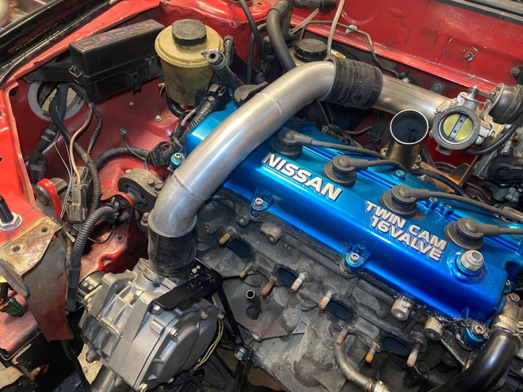
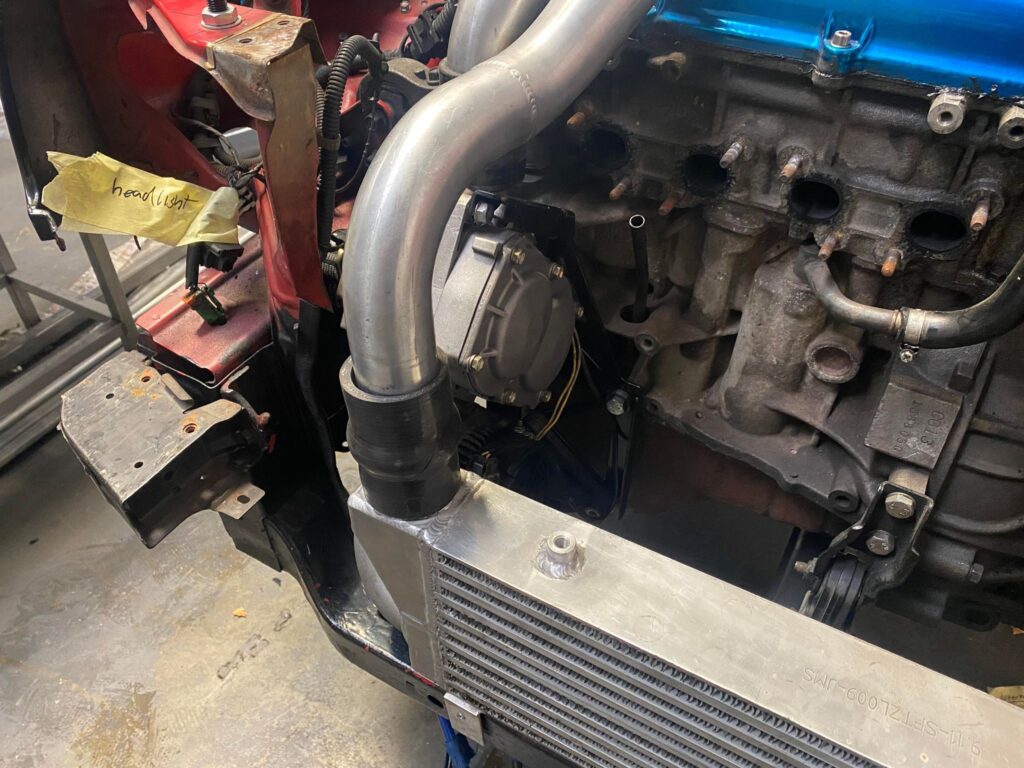
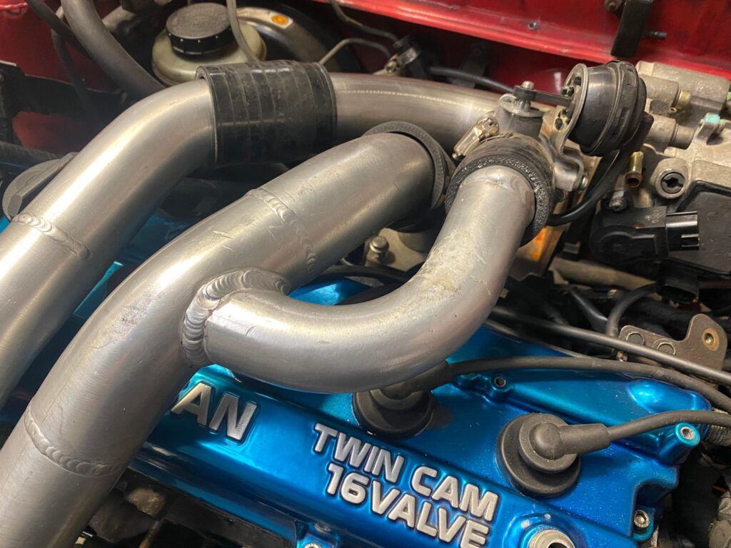
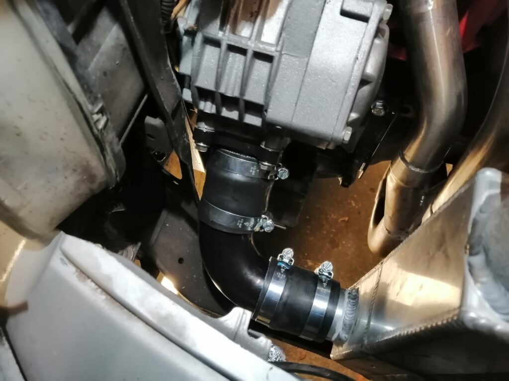
Now you can install the first cross over pipe
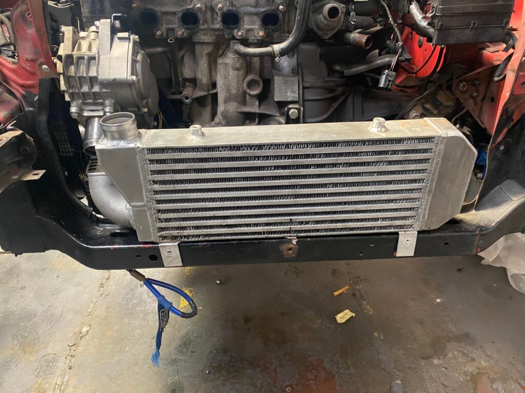
Now install the intercooler. The intercooler will use an existing mounting hole on the front panel and an existing hole on the slam panel, under the bonnet catch. Your intercooler will look dramatically different to the one in the picture. Yours will be Thicker, Slimmer and Taller
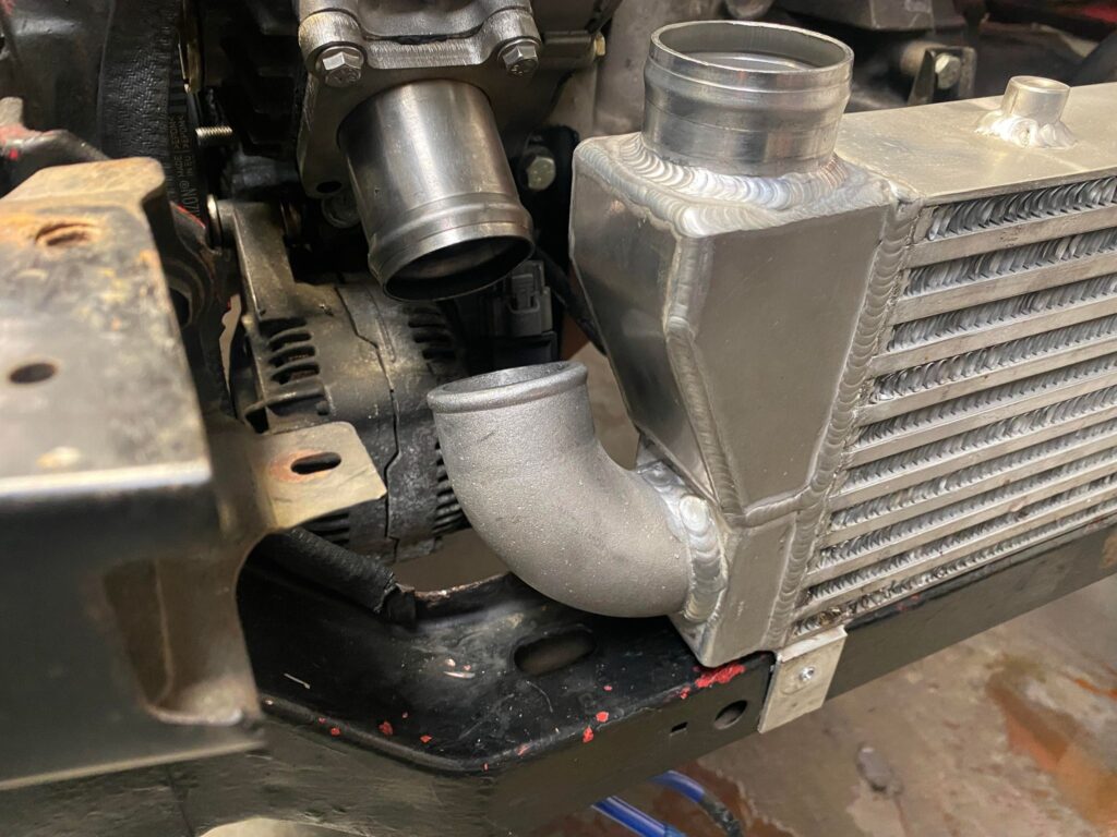
For the connection between the intercooler and the supercharger, your kit will differ to the one in the image below.
In your kit will be two 90 degree elbows. You will want the larger of the two. Use 2 silicone joiners and this elbow to connect the supercharger to the intercooler.
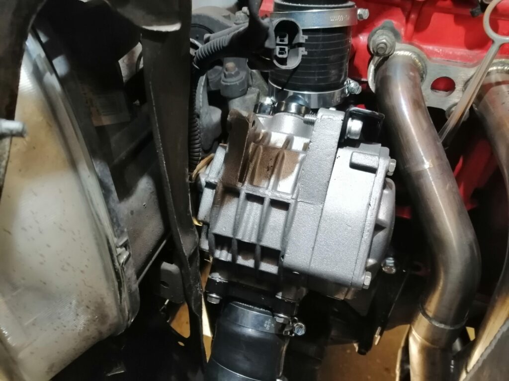
Now we can install the secondary crossover pipe.
Your kit will differ for the bypass valve connection. Instead of a single solid tube as pictured.
The smaller tube that branches off the main larger tube is now replaced with a 90 degree elbow (The smaller of the two) and 2 silicone joiners.
The elbow will only fit one way, with the longer side of the elbow connecting to the bypass valve, and the short side connecting to the crossover pipe.
The crossover pipe joins to the inlet manifold elbow we installed earlier using a silicone joiner.
If you have a Coil pack Model, there will be 4 M6 Dome headed bolts to replace the Hex bolts in the coil packs. The clearance is tight between the coil packs on the secondary crossover pipe.
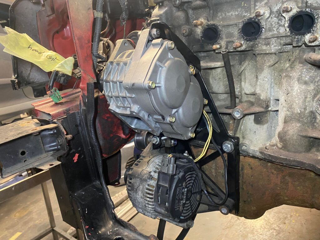
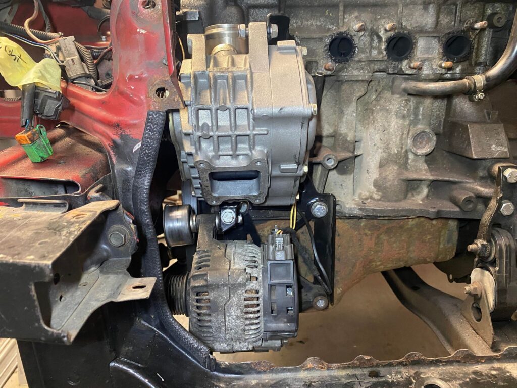
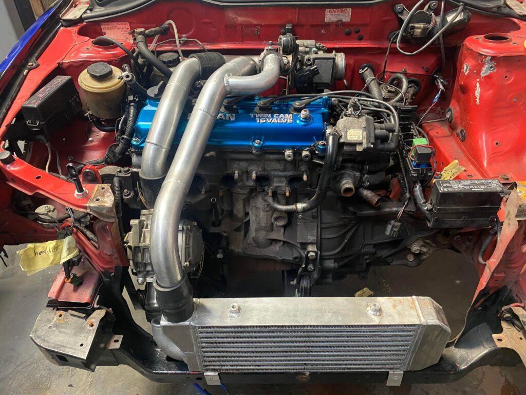
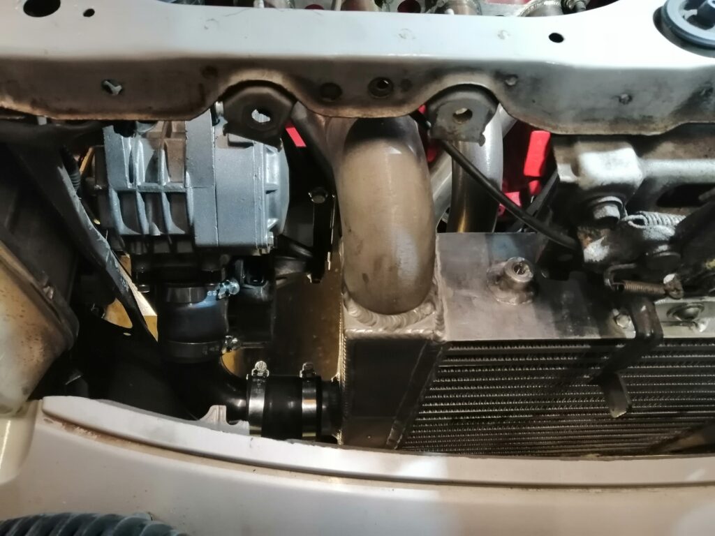
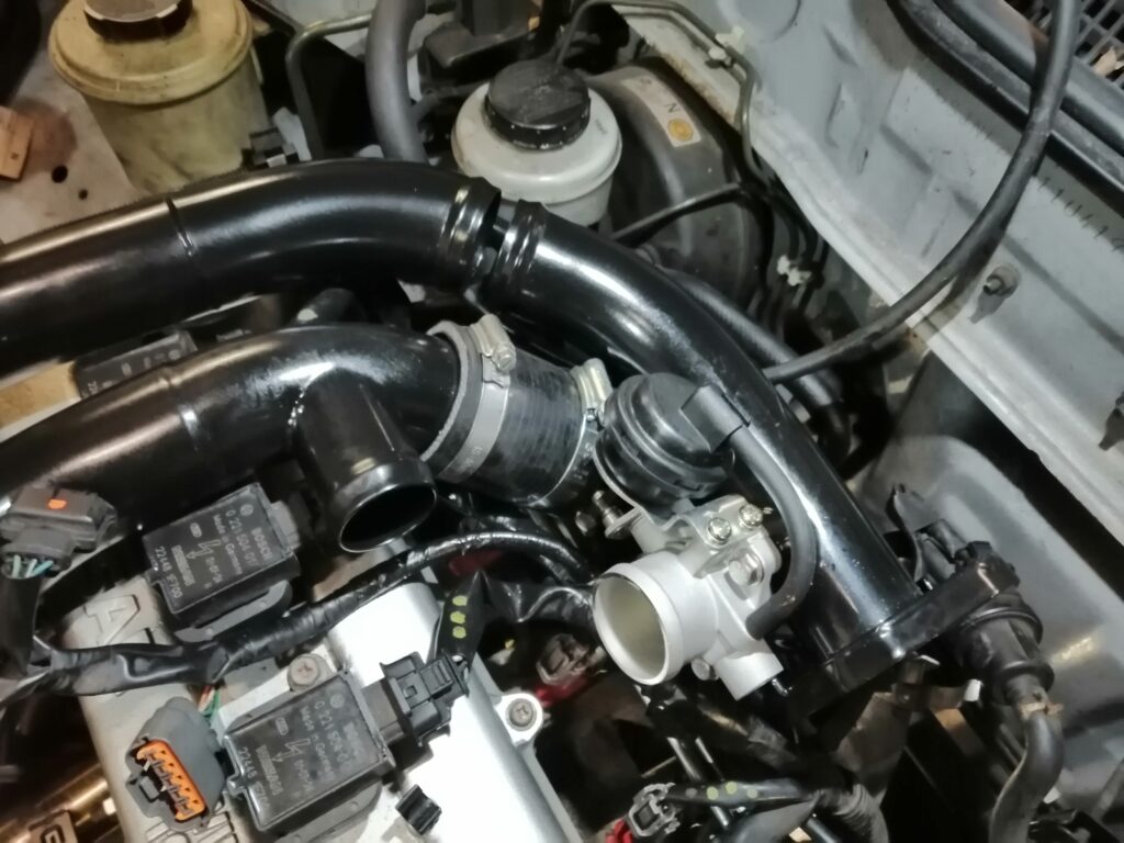
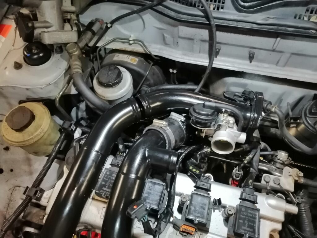
Your setup should now look similar to the below image.
Next, install the coolant hoses to the outlets on the throttle body that we replaced earlier in the guide.
Connect the hose from the RIGHT side to the elbow on the throttle body we rotated earlier. Cut to hose to length.


Then install the other coolant hose to this port on the throttle body.
Now install the throttle body cable. There’s no need to modify anything for this, simple route the cable down as it exits the firewall, under the inlet manifold and loop it back on itself and into the bracket.
If the cable appears stiff, Adjust as needed and lubricate the inside of the cable.
Don’t forget to plug in the MAF and TPS Sensor plugs.
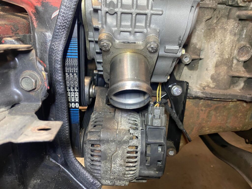
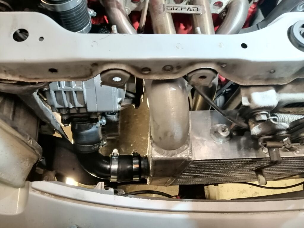
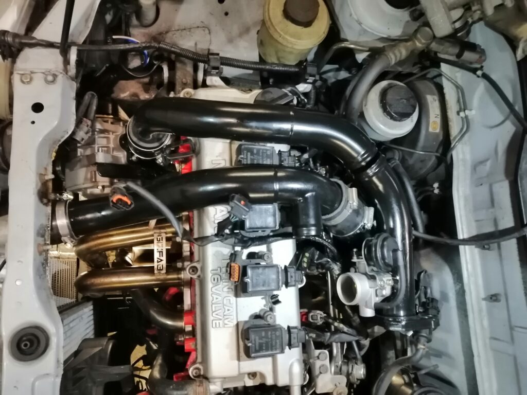
From here, your kit should be in a position to be started for the first time.
Here is an example of a completed install of the Kit you will received.

FMU INSTALL
Included in the kit is a bracket that will allow you to mount the FMU. We suggest mounting it to the lip on the firewall seam.
We need to re-route the fuel hoses.
The Factory Routing is from the Fuel Filter (The Fuel Feed) to the inlet side of the Fuel Rail (Not the Regulator), Then from the Regulator to the fuel return on the bottom of the firewall. Follow both of these hoses so you understand there routing.
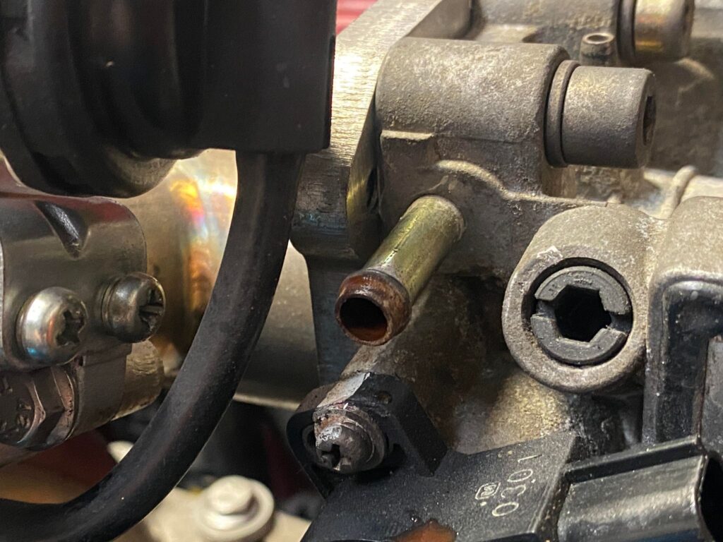
As the FMU Is a Fuel Regulator, we need to remove the factory fuel regulator. We will supply the adapter chosen when you ordered the kit. Install the adapter with the barb pointing towards the firewall. Below are images of both adapters for reference.
The Factory Fuel Feed to the rain can remain as it is from the factory.
From the adapter you have just installed, Route a hose from this outlet to the SIDE of the FMU Unit.
From the Bottom of the FMU Unit, Route a section of hose from here to the fuel return to the tank
If you have a Plastic FMU, In the kit will be supplied a section of blanking hose to be installed on the additional side port.
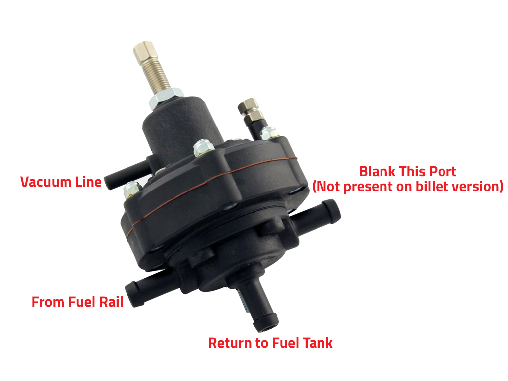
The vacuum line installed earlier, connects to the vacuum port on the FMU. If you want to install a Boost Gauge, you can Tee into this vacuum hose.
Setting up the FMU
At this point, we are assuming you have installed new injectors and a new fuel pump. For the Distributer models we recommend sourcing and installing GA16DE Injectors. For coil pack, QG18 Injectors. An uprated Fuel pump is advised, there are many available on the market, Please do some research before purchasing.
Why a new fuel pump? the FMU is going to demand 2.5-3x more fuel pressure than the standard fuel pressure. Asking a 20+ Year old fuel pump to suddenly work harder than it has been doing for several years can cause the pump to fail rather quickly and loss of fuel whilst the engine is in boost can melt the engine.
Once the engine is idling, set the base fuel pressure to 2 bar taking note of the fuel pressure gauge.
Now to adjust the GAIN pressure. Without a rolling road, it will be difficult to set the Gain pressure. The only solution to set gain pressure is to aggressively rev the engine and keep a keen eye on the fuel pressure gauge as you make adjustments to the gain.
The small Hex brass fitting on the top of the FMU is the GAIN adjustment. It is very sensitive to adjustments, so adjust the gain in VERY Small increments of approx 1/16th at a time.
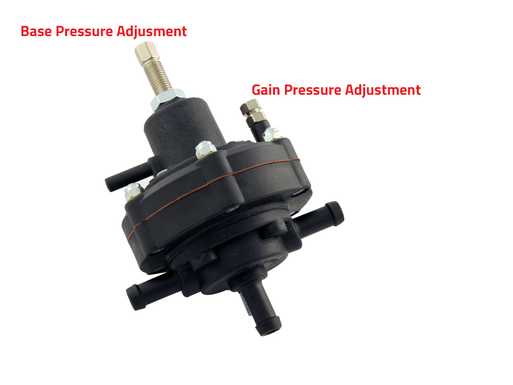
You are aiming for 4.5/5 BAR of fuel pressure when you stab the throttle.
If using a rolling road, adjust the screw whilst the engine is held in a constant loaded state.
Remember to tighten the lock nut when finished.
OVER adjusting the FMU Gain Screw WILL Damage the Diaphragm inside the FMU and you will be unable to set reliable fuel pressure. This damage is NOT Covered by warranty
Why do we use the FMU and what does it do?
FMU is a budget friendly way of adjusting the fuelling without spending thousands on a Standalone ECU. With a standalone ECU you would typically adjust the injector duty cycle to inject more fuel into the engine. By we need to inject more fuel into the engine to compensate for the additional volume of air/ boost we are forcing into the engine.A Typical fuel regulator will increase fuel pressure on a 1:1 Ratio. So for every 1 psi of boost, fuel pressure is increased by 1psi, this is great if you can adjust the duty cycle as above.
An FMU However will allow you to adjust this ratio up to a 1:14 Ratio. So for every 1psi of boost, we have the potential to increase fuel pressure up to 14psi.
By increasing the Gain fuel pressure, we are increase the fuel pressure head behind the injector, so when the ECU opens the injector as per standard programming, the increased pressure will force more fuel through the injector, increasing the amount of fuel injected into the cylinder. Its not ideal and is considered a rather crude method.
So if this is the case, why do we need bigger injectors? We still need to increase the capacity of the injector to achieve a decent fuel level needed. It’s an old-school method of increasing fuelling, but it is budget friendly.
With a standalone ECU, you would adjust the duty cycle of the injectors, Duty Cycle is the amount of Time the injector is Open and therefore increasing the amount of fuel injected. There is a relationship between the size of the injector and the Duty cycle. It gets a bit technical and it’s a bit much for this guide.
An FMU Isn’t needed when using an aftermarket ECU.
Potential Running Issues
If the Belt is Squealing, Possible cause could be either Insufficient Belt tensioner or contaminated belt. Remove belt, Clean Crank Pulley, Supercharger Pulley, Alternator Pulley Tighten and idler roller. Inspect belt for contamination.
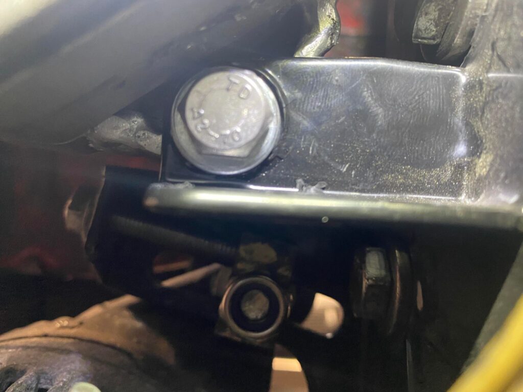
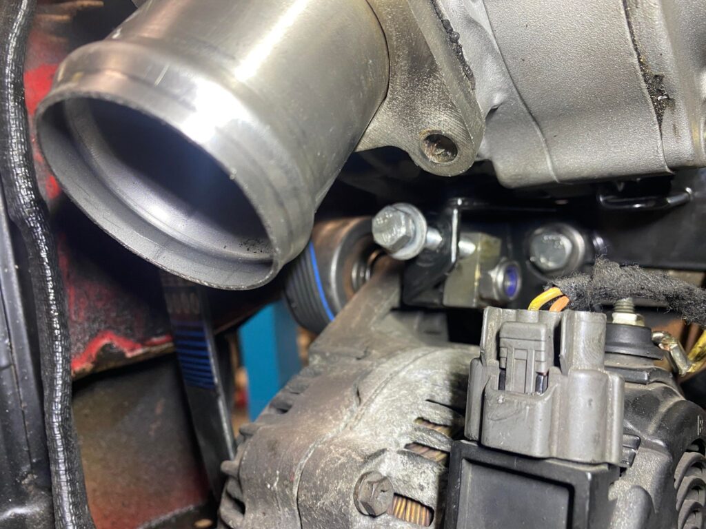
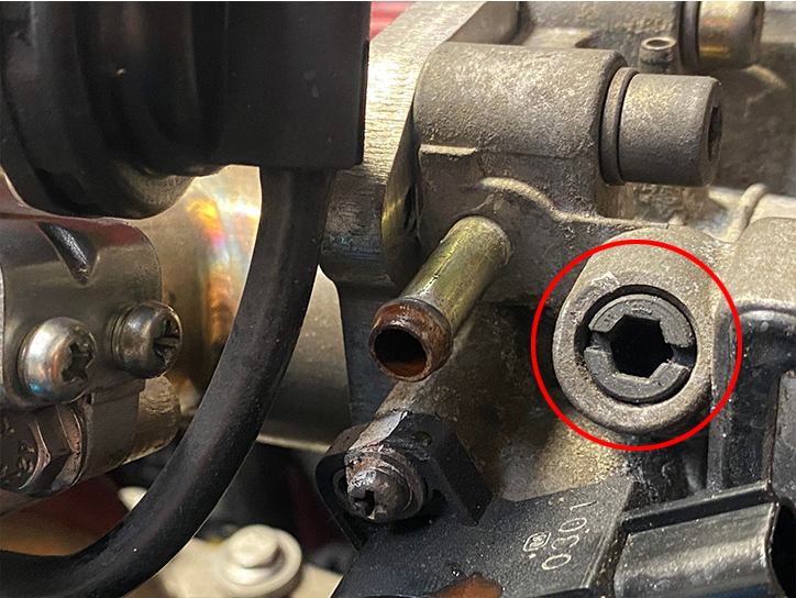
If there are issue with idling on Distributer models. You can adjust the idle bump stop on the throttle cable quadrant and/or adjust the air bypass screw. Screw shown below.
Unfortunately, the Bypass screw isn’t present on coil pack models and therefore no way to adjust air bypass without a standalone ECU.
An unfortunate Trait when using an FMU is that the ECU cannot calculate the additional volume of air created by the crossover pipe work and the intercooler.
Because of how the supercharger has to be installed on the Micra with the crossover pipes, we have effectively made the inlet manifold larger. The ECU will be calibrated for the standard issue volume of the inlet manifold.
We have now increased the volume of the inlet manifold roughly 4x. So if the inlet manifold held 1 Liter of Air, It now holds 4 Liters of air.
The ECU However will still only inject enough fuel for the calibrated 1 Liter of Air and not the 4 Liters of air it now has. This means the engine has a tendency to cut out when coming down to idle speed. This can be compensated by a quick blip or two of the throttle to ease the engine into idle speed rather than letting the engine come to idle naturally.
Another way to combat this is to force a higher idle speed, either by the throttle stop or adjusting the air bypass.
This is the unfortunately trade off of using the FMU. The only way to completely fix this would be to purchase and install a standalone ECU and take the car for a proper mapping session to re-calculate the inlet manifold volume. This can be costly in the region of £1000+, so the FMU Will saves you money.
Its worth noting the Distributer ECU is simple compared to the Coil pack ECU. The Coil pack ECU appears to be able to know that the inlet volume has changed and it sometimes does not like this and will cause an erratic idle. The Distributer ECU However seems to be unfazed. Once again, the only way to fix this would be a standalone ECU
Can i spin the charger for more Boost?
For those wondering if you can spin the charger to create more boost.
Yes, it’s entirely possible with a larger crank pulley from a GA/QG Series engine. However I would advise against doing so.
With the current pulley ratio, the supercharger is running around 85% of its recommended maximum RPM @ 6500rpm with the standard crank pulley.
Spinning the supercharger faster to create more boost will also increase the amount of heat generated by the unit which will create less boost intake temperatures rise and the tolerances start to loosen up. Over driving the supercharger unit will dramatically reduce the life span of the unit.. We will not warrant a supercharger that has evidence of overheating/ over speed.
And that concludes the installation guide. Happy boosting!
